
BUS DUCT & CABLE BUS DUCTS
INTRODUCTION
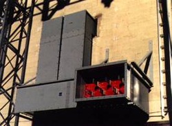
Cable bus duct systems are used to distribute large blocks of power efficiently and economically. Cable bus duct is designed for interconnecting groups of Metal-Enclosed or Metal-Clad Switchgear, power transformers, generators or other related equipment.
General Switchgear & Controls Ltd. manufacturers cable duct systems and necessary fittings up to 6000A and 15000V.
STANDARDS
Cable duct systems are designed to meet the following standards:
PRODUCTS
General Switchgear & Controls Ltd. manufactures assembled or field loaded cable duct systems and necessary fittings rated 6000A maximum, 15kVAC maximum, 2kV DC maximum, single phase or 3 phase, 600V, 3 wire 5kV, 15kV with or without neutral using insulated copper or aluminum cables.
The cable duct enclosure may be ventilated or totally enclosed, designed for indoor or outdoor application, maximum distance between supports 12 Feet inside (3.65M), 10 Feet outside (3M). The cable duct may be installed horizontally or vertically.
DESCRIPTION
The bus duct enclosures are made of fabricated aluminum enclosure loaded with insulated cables supported and segregated by insulated cable support assemblies fastened to the enclosure at suitable intervals. Each straight length and necessary fitting is fully fitted at the factory. The factory assembled parts are installed in the field in accordance with the manufacturers instructions and hardware provided.
CONSTRUCTION
The two side walls are the main structural members and are made of extruded aluminum 0.08 inch to 0.125 inch (2-3mm) thick dependent on duct enclosure height. The top and bottom covers are made from aluminum sheet 0.08 inch (2mm) thick. The covers are joined by an overlap joint. Cable support systems and channels are provided at 36 inch (915mm) intervals or less. The vertical channel for cable supports are placed on the top of the lower horizontal channel and against the vertical side wall.
CABLE SUPPORTS
The cable supports are made from glass reinforced polyester, molded with two sets of three or six cable grooves, one set on each of the two opposite sides. Each cable support has one through hole approx. 7/16 inch (1mm) diameter.
The cable supports are placed in the supporting channels in pairs. The alternate layer of cable and cable supports are installed with the cable support alternated in direction with the grooves facing each other. The grooves are specially designed (smaller than the semi circles), so that the cables are clamped before the two supports touch. The cable is thus positively clamped by the clamping channel placed on the top block.
This top channel is bolted through the side wall and the block channel support in the cable that can be clamped is 1 inch (25mm) minimum and 2 inch (650mm) maximum.
COVER
The top cover is louvered aluminum sheet of 0.08 inch (2mm) thick approx. 36 inch (915mm) in length and joined by an overlap. The top covers are fixed to the flange of the vertical walls using stainless steel screws.
BENDS, CORNERS AND FLANGES
Flange is constructed from 3/16 inch (5mm) aluminum sheet and sized to suit the cable duct enclosure. Adjacent to this flange a weather seal plate in which aluminum tubes welded in place to match the cable layout pattern of the cable duct, sealing is ensured by heat shrinking of 8 inch (20mm) long tube between the aluminum tube in the flange and cables in the cable bus duct.
Whenever the cable bus duct passes through walls or ceiling an internal fire barrier (1/2 hour rated) is provided as per CE Code Part 1. Special barriers up to 3 hours can be provided. For vertical run cable bus duct, drainage holes are provided.
CABLE JOINTS AND SPLICES
Factory or field joints are made as follows:
CABLE JOINT INSULATION
5KV AND BELOW (INDOOR)
High density polyethylene tube 0.125 inch (3mm) thick approx. 30 inch (762mm) length is used over the joints and is held in position by cable support assemblies on each side of the joint.
5KV AND HIGHER (ALL OUTDOOR)
Raychem heat shrink insulation kits or equivalent as described in manufacturer's literature are used.
GROUND BONDING
Each section of the cable bus enclosure is bonded by the bolted joint between sections. Bolted are secured by external toothed plated lock washers which bite into the side walls.
Each expansion joints is jumpered by a 18 inch (457mm) length of cable on each side of the duct and size of the cable selected in accordance to CE Part 1 table 16. The cable is terminated using compression type lugs and fixed on each side of the cable bus ducts using 3/8-16 inch bolts and external toothed lock washers.
CABLE
Power cables of size, type, insulation and quantity per phase will be used as shown in the manufacturers catalog. CSA approved cables will be used.
MARKING
On each finished lengths of cable bus enclosure a Nameplate containing the manufacturer's name, type, current rating of phase and neutral cable where applicable, BIL rating where applicable) and maximum distance between supports 12 Feet indoor, 10 Feet outdoor is provided.
Complete instructions for making field joints is shipped with each termination kit.
FACTORY TESTS
Each completed length of cable duct including fittings is tested as follows:
Cable bus duct systems are used to distribute large blocks of power efficiently and economically. Cable bus duct is designed for interconnecting groups of Metal-Enclosed or Metal-Clad Switchgear, power transformers, generators or other related equipment.
General Switchgear & Controls Ltd. manufacturers cable duct systems and necessary fittings up to 6000A and 15000V.
STANDARDS
Cable duct systems are designed to meet the following standards:
- C.S.A. C22.2 No. 27: Busways.
- C.S.A. C22.2 No. 201: Metal Enclosed High Voltage Busways.
- CSA C22.2 No. 0-M1982: General requirement - Canadian Electrical code.
0.4-M1982 - Bonding and grounding of electrical equipment.
27-1973 - Bonding. - A.N.S.I. C37.20 a,b,c & d. (I.E.E.E. Std. No. 27): Switchgear Assemblies Including Metal Enclosed Bus.
- N.E.M.A. WC7 (I.C.E.A. Stds. Publication No. S-66-524) Cross-Linked-Thermosetting-Polyethylene Insulated Wire and Cable for the Transmission and Distribution of Electrical Energy.
- N.E.M.A. WC8 (I.C.E.A. Stds. Publication No. S-68-516) Ethylene-Propylene-Rubber Insulated Wire and Cable for the Transmission and Distribution of Electrical Energy.
- UL-1072 Standard for Medium Voltage Solid Dielectric Cable.
PRODUCTS
General Switchgear & Controls Ltd. manufactures assembled or field loaded cable duct systems and necessary fittings rated 6000A maximum, 15kVAC maximum, 2kV DC maximum, single phase or 3 phase, 600V, 3 wire 5kV, 15kV with or without neutral using insulated copper or aluminum cables.
The cable duct enclosure may be ventilated or totally enclosed, designed for indoor or outdoor application, maximum distance between supports 12 Feet inside (3.65M), 10 Feet outside (3M). The cable duct may be installed horizontally or vertically.
DESCRIPTION
The bus duct enclosures are made of fabricated aluminum enclosure loaded with insulated cables supported and segregated by insulated cable support assemblies fastened to the enclosure at suitable intervals. Each straight length and necessary fitting is fully fitted at the factory. The factory assembled parts are installed in the field in accordance with the manufacturers instructions and hardware provided.
CONSTRUCTION
The two side walls are the main structural members and are made of extruded aluminum 0.08 inch to 0.125 inch (2-3mm) thick dependent on duct enclosure height. The top and bottom covers are made from aluminum sheet 0.08 inch (2mm) thick. The covers are joined by an overlap joint. Cable support systems and channels are provided at 36 inch (915mm) intervals or less. The vertical channel for cable supports are placed on the top of the lower horizontal channel and against the vertical side wall.
CABLE SUPPORTS
The cable supports are made from glass reinforced polyester, molded with two sets of three or six cable grooves, one set on each of the two opposite sides. Each cable support has one through hole approx. 7/16 inch (1mm) diameter.
The cable supports are placed in the supporting channels in pairs. The alternate layer of cable and cable supports are installed with the cable support alternated in direction with the grooves facing each other. The grooves are specially designed (smaller than the semi circles), so that the cables are clamped before the two supports touch. The cable is thus positively clamped by the clamping channel placed on the top block.
This top channel is bolted through the side wall and the block channel support in the cable that can be clamped is 1 inch (25mm) minimum and 2 inch (650mm) maximum.
COVER
The top cover is louvered aluminum sheet of 0.08 inch (2mm) thick approx. 36 inch (915mm) in length and joined by an overlap. The top covers are fixed to the flange of the vertical walls using stainless steel screws.
BENDS, CORNERS AND FLANGES
Flange is constructed from 3/16 inch (5mm) aluminum sheet and sized to suit the cable duct enclosure. Adjacent to this flange a weather seal plate in which aluminum tubes welded in place to match the cable layout pattern of the cable duct, sealing is ensured by heat shrinking of 8 inch (20mm) long tube between the aluminum tube in the flange and cables in the cable bus duct.
Whenever the cable bus duct passes through walls or ceiling an internal fire barrier (1/2 hour rated) is provided as per CE Code Part 1. Special barriers up to 3 hours can be provided. For vertical run cable bus duct, drainage holes are provided.
CABLE JOINTS AND SPLICES
Factory or field joints are made as follows:
- Compression type cable connector bolted together and insulated
- Compression type cable splice insulated.
CABLE JOINT INSULATION
5KV AND BELOW (INDOOR)
High density polyethylene tube 0.125 inch (3mm) thick approx. 30 inch (762mm) length is used over the joints and is held in position by cable support assemblies on each side of the joint.
5KV AND HIGHER (ALL OUTDOOR)
Raychem heat shrink insulation kits or equivalent as described in manufacturer's literature are used.
GROUND BONDING
Each section of the cable bus enclosure is bonded by the bolted joint between sections. Bolted are secured by external toothed plated lock washers which bite into the side walls.
Each expansion joints is jumpered by a 18 inch (457mm) length of cable on each side of the duct and size of the cable selected in accordance to CE Part 1 table 16. The cable is terminated using compression type lugs and fixed on each side of the cable bus ducts using 3/8-16 inch bolts and external toothed lock washers.
CABLE
Power cables of size, type, insulation and quantity per phase will be used as shown in the manufacturers catalog. CSA approved cables will be used.
MARKING
On each finished lengths of cable bus enclosure a Nameplate containing the manufacturer's name, type, current rating of phase and neutral cable where applicable, BIL rating where applicable) and maximum distance between supports 12 Feet indoor, 10 Feet outdoor is provided.
Complete instructions for making field joints is shipped with each termination kit.
FACTORY TESTS
Each completed length of cable duct including fittings is tested as follows:
- Dielectric test based on CSA C22.2 No. 201-M1984 for system voltage 751V to 38kV for system.
- Voltage between 751V, test voltage to be 24kV DC.

